I bought some light in Turkey. They are awesome! Turkish wiring however leaves a lot to be desired for. First step was to rip out the speaker wire that had been used for the power! The joints had just been twisted together and wrapped with electrical tape!!!
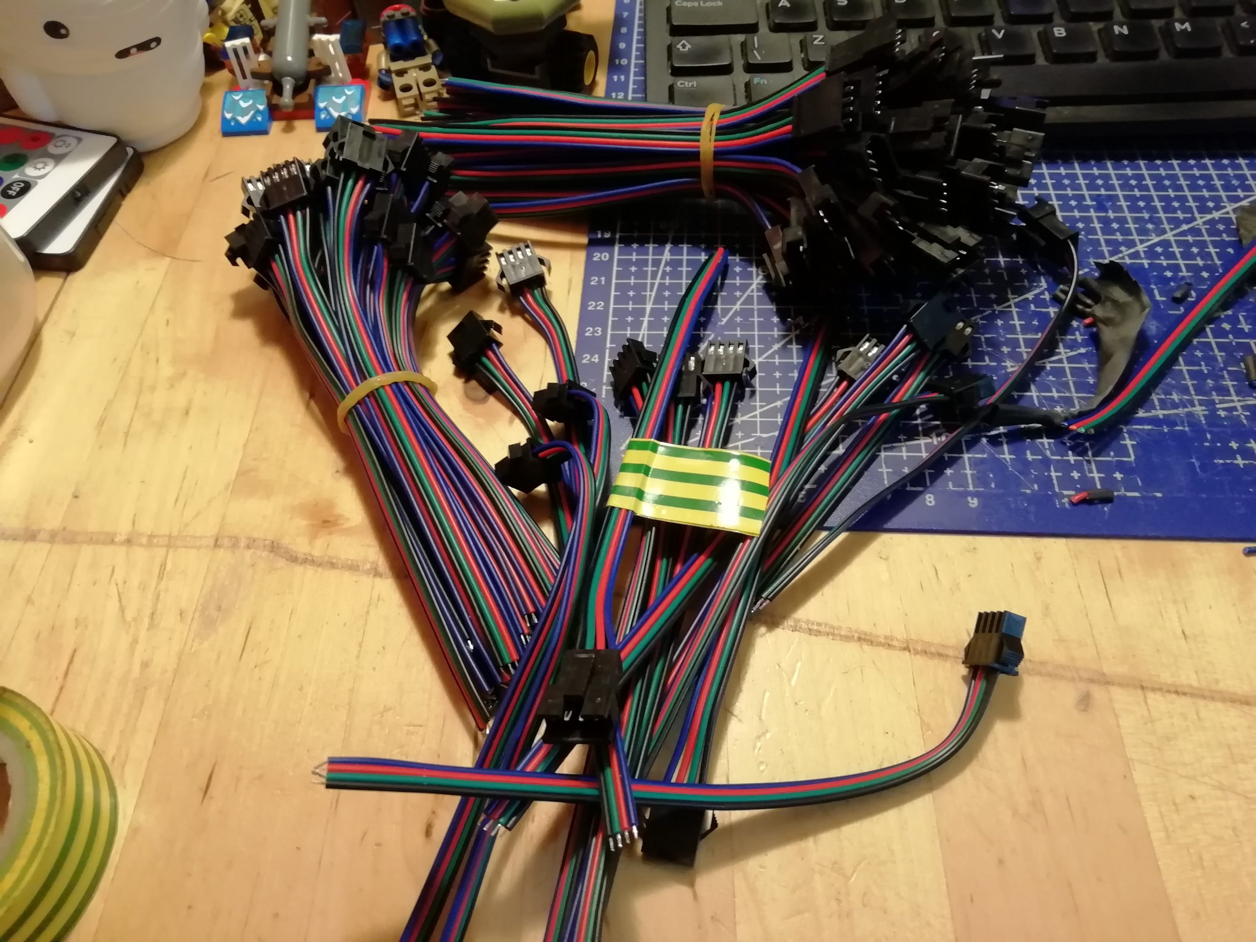
I used some lever wago connectors for the junctions with 2-core wire running to each light and then 3-core running from the power source to the main body of the light. Live and neutral going to wago connectors and earth going to a bolt I drilled and fitted to the main body…. nothing was earthed before! The wago connectors were fixed to the main body of the light using hot glue.

5 way lever Wago connector, suitable for fine stranded cable.

The wago connectors were only 5 way and annoyingly I needed 6 for each of live and neutral (5 lights + incoming power). I ended up using a five way and a 3 way connector for each channel, daisy chained together. 8 connections per channel where I needed 6 and 2 were used up by the daisy chaining.
This left some exposed parts rather garish colours so I base coated them in black and dry-brushed over them in gold so that they blended in. A bit messy but you won’t see it when its up near the ceiling. I just really wanted to tone down the bright colours. I may yet paint the cables black bit thats probably overkill. You can also see the ground bolt I added between the wago connectors.

Here you can see a close up of the earth bolt after it has been painted.

Its alive!!

Now to drill up through the ceiling where I want it, a hole big enough to run the cable through. That has allowed me to find where it is going to go from in the attic. I’ve added a noggin (cross member between 2 rafters) over the hole for the power cable. This means I could go back and drill the power cord hole, this time going through the noggin as well.
Now I have somewhere to feed the power cable and I can screw an 80mm hook through the plaster board and into the noggin to hang the light from.

Sod’s law I bought 40mm long screws but the ceiling is very old with a layer of plasterboard over the top of the original lath and plaster. This means I need about 60 mm just to get through the plaster and up to the noggin! Its Easter, 2 bank holidays, they aren’t stocked in screwfix or toolstation so I’ve got to buy them online with delivery in 6 days. <Insert screaming gif>.
Once its fixed to the ceiling I’ll splice power off the existing light using more wago connectors.